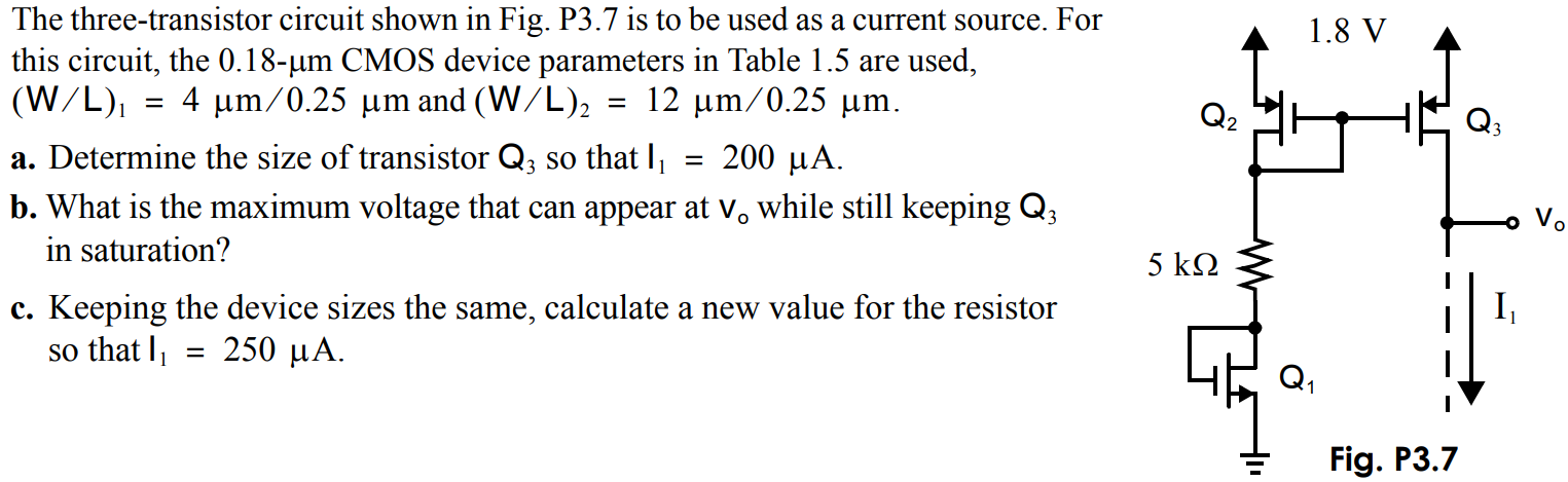
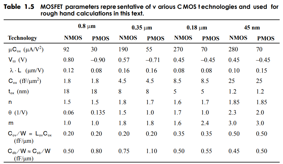
The three-transistor circuit shown in Fig. P3.7 is lo be used as a current source. For this circuit, the. 0.18-µm CMOS device parameters in Table 1.5 are used, (W/L)1 = 4 µm/0.25 µm and (W/L)2 = 12 µm/0.25 µm. a) Determine the size of transistor so that I1 = 200 µA. b. What is the maximum voltage that can appear at Vo while still keeping in saturation? c. Keeping the device sizes the same, calculate a new value for the resistor so that I1 = 250 µA.
You'll get a detailed, step-by-step and expert verified solution.
 Work With Experts to Reach at Correct Answers